Adding Smaller Debris and Dust
01.1 We will continue by adding in a new group with the name of ‘Box Front Back’ while renaming the old ‘Box‘ Group as ‘Box Ryt Lft’. Remove the ‘Frnt’ and ‘Back’ geometry from the ‘Box Ryt Lft’ group and add them to the ‘Box Front Back’ group. Inside the ‘Obj.To Particle’ parameters select ‘Box Ryt Lft’ as the group from drop down menu and select ‘Object to Particle’ as the track. Also check ‘Instance Shape’ and hit ‘Hide’ in the end. This will enable us to apply materials on these two groups separately as the box model had two separate UVW Unwraps for Front and Back parts and for Left and Right parts.
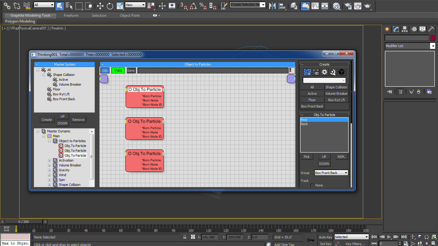
Fig 01.1
01.2 Add in a new Dynamic Set with the name of ‘Materials’ inside ‘Main’ Dynamic Set and add in all the groups from right click menu one by one ‘Groups > Shape Collision’, ‘Groups > Floor’, ‘Groups > Box Ryt Lft’, ‘Groups > Front Back’. Now we will add in 4 different ‘Shape Material’ Material Operators inside the Material Dynamic Set from right click menu by selecting ‘Operators > Material > Shape Material’.

Fig 01.2
01.3 Link each one of those Shape Materials to the Group Nodes. Select the Shape Material node linked to the ‘Box Front Back’ group and inside the Shape Material parameters click ‘Materials’ button. Select the ‘Material # 24 (VrayMtl)’ from the Material/Map Browser. Similarly select the ‘Material # 23 (VrayMtl)’ for ‘Box Ryt Lft’ group, ‘Material # 18 (VrayMtl)’ for ‘Floor’ group and ‘Material # 24 (VrayMtl)’ for ‘Shape Collision’ Group.
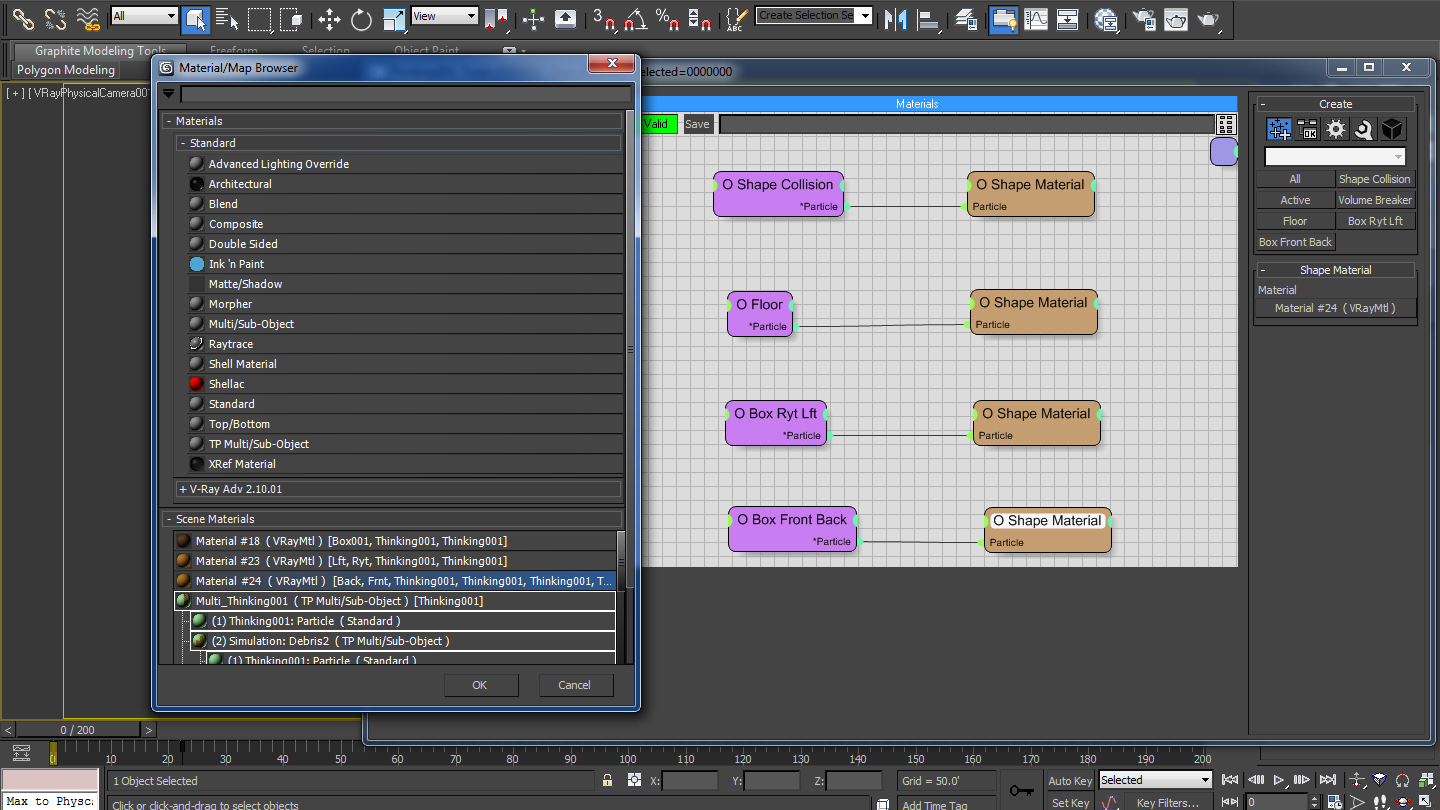
Fig 01.3
02.1 Select the ‘Fragment’ inside ‘Activation’ Master Dynamic and bring down the ‘Smoothing Angle’ to 125.0 in order to get some more pieces or fragments out of the Cardboard Box. Also decrease the ‘Radius’ to 50%.
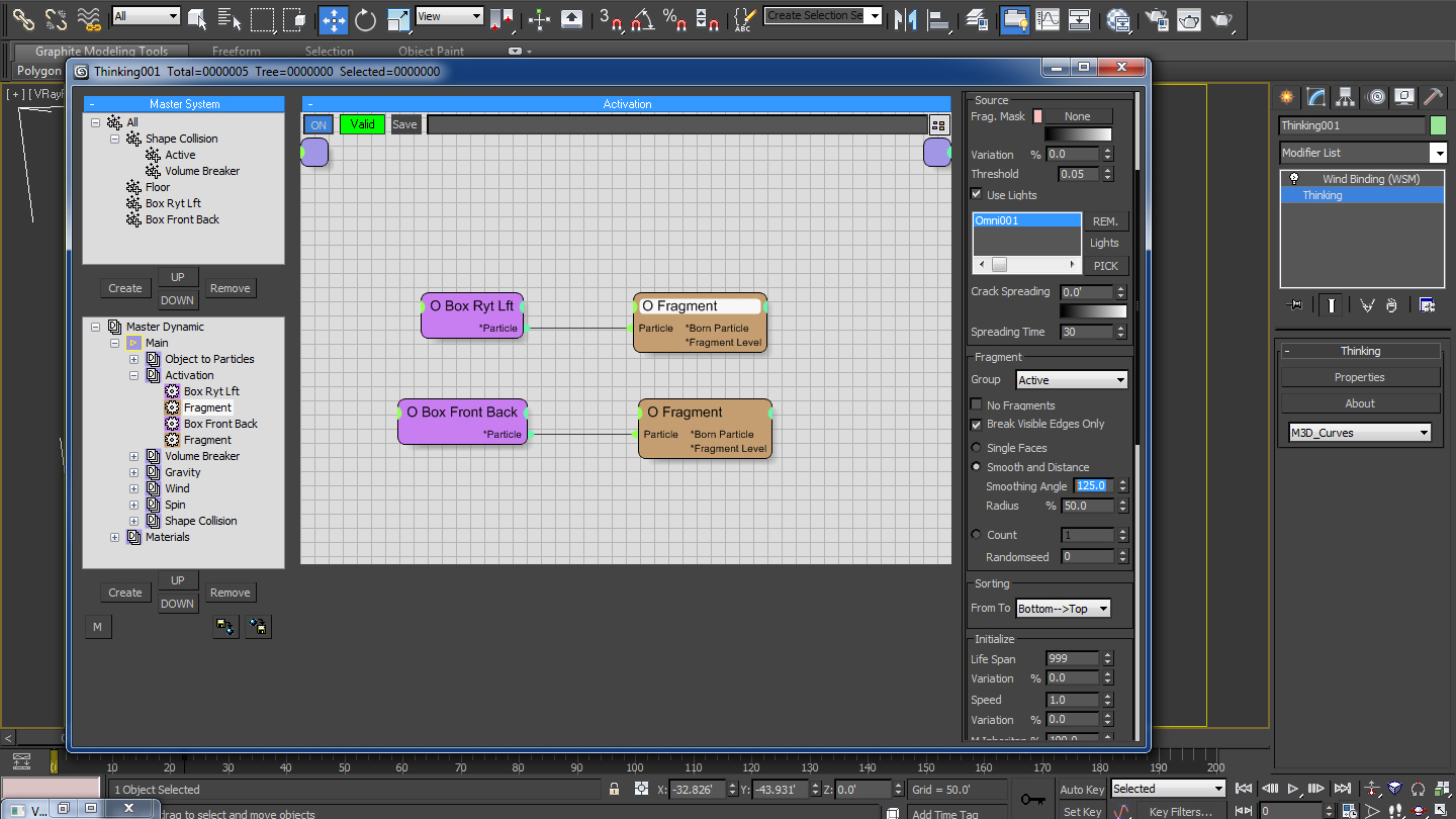
Fig 02.1
02.2 Select the ‘Active’ Sub Group from the ‘Shape Collision’ Group and bring down the ‘Dynamic Friction’ and ‘Static Friction’ to 30.0 each. Bring up the ‘Elasticity’ to 35.0.
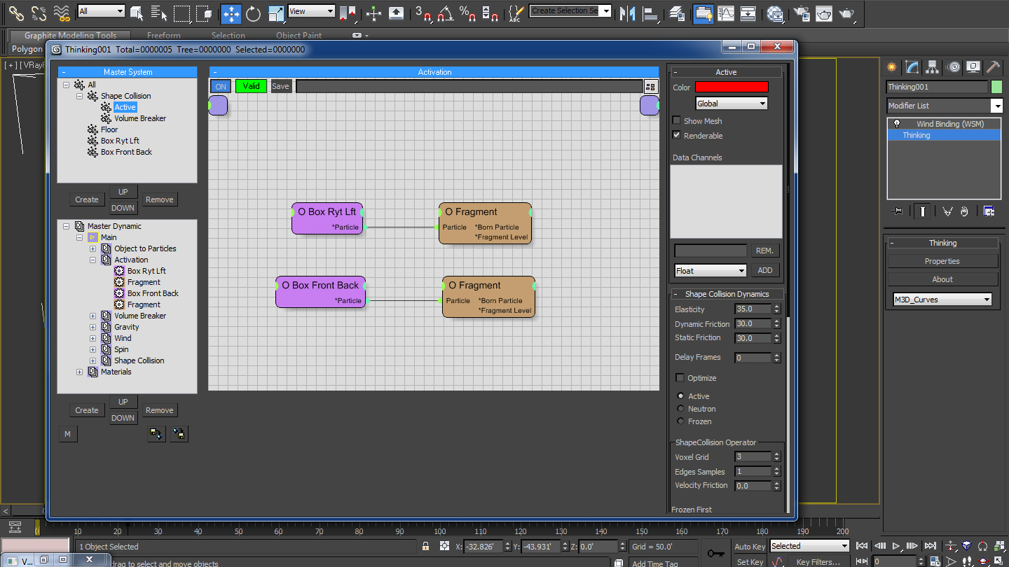
Fig 02.2
03.1 Create a copy of ‘Volume Breaker’ Dynamic Set inside the ‘Main’ Dynamic Set by selecting it and dragging it while pressing the Shift Key. Rename it as ‘Volume Breaker Debris’. Also create a new group with the same name i.e. ‘Volume Breaker Debris’.

Fig 03.1
03.2 Select ‘Active’ inside the ‘Volume Breaker Debris’ Dynamic Set and change the ‘Group’ to ‘Volume Breaker’. Similarly select ‘VolumeBreak’ inside the ‘Volume Breaker Debris’ Dynamic Set and change the ‘Group’ to ‘Volume Breaker Debris’. Increase the ‘Activate’ option inside ‘VolumeBreak’ parameter to 70%. Also increase the Raster and Density values to 15% and 3000 respectively.

Fig 03.2
03.3 In the end set the ‘Frames’ value parameter of ‘H Timer’ for ‘Volume Breaker Debris’ Dynamic Set to 8 and for ‘Volume Breaker’ Dynamic Set to 6, in order to get finer pieces. We will now cache the simulation by selecting the ‘Cache Record’ option from the right click menu of ‘Main’ Dynamic Set, after removing the current cached simulation from the memory through ‘Cache Unset’ option of right click menu.

Fig 03.3
04.1 Create a new Dynamic Set with the name of ‘Dust’ under Master Dynamic Set. We will create Dust from the ‘Active’ group, hence we will bring in ‘Active’ group from the right click menu ‘Groups > Active’. Append a ‘Position Born’ Operator Generator from the right click menu ‘Operators > Generator > Position Born’, to the ‘Particle’ parameter.
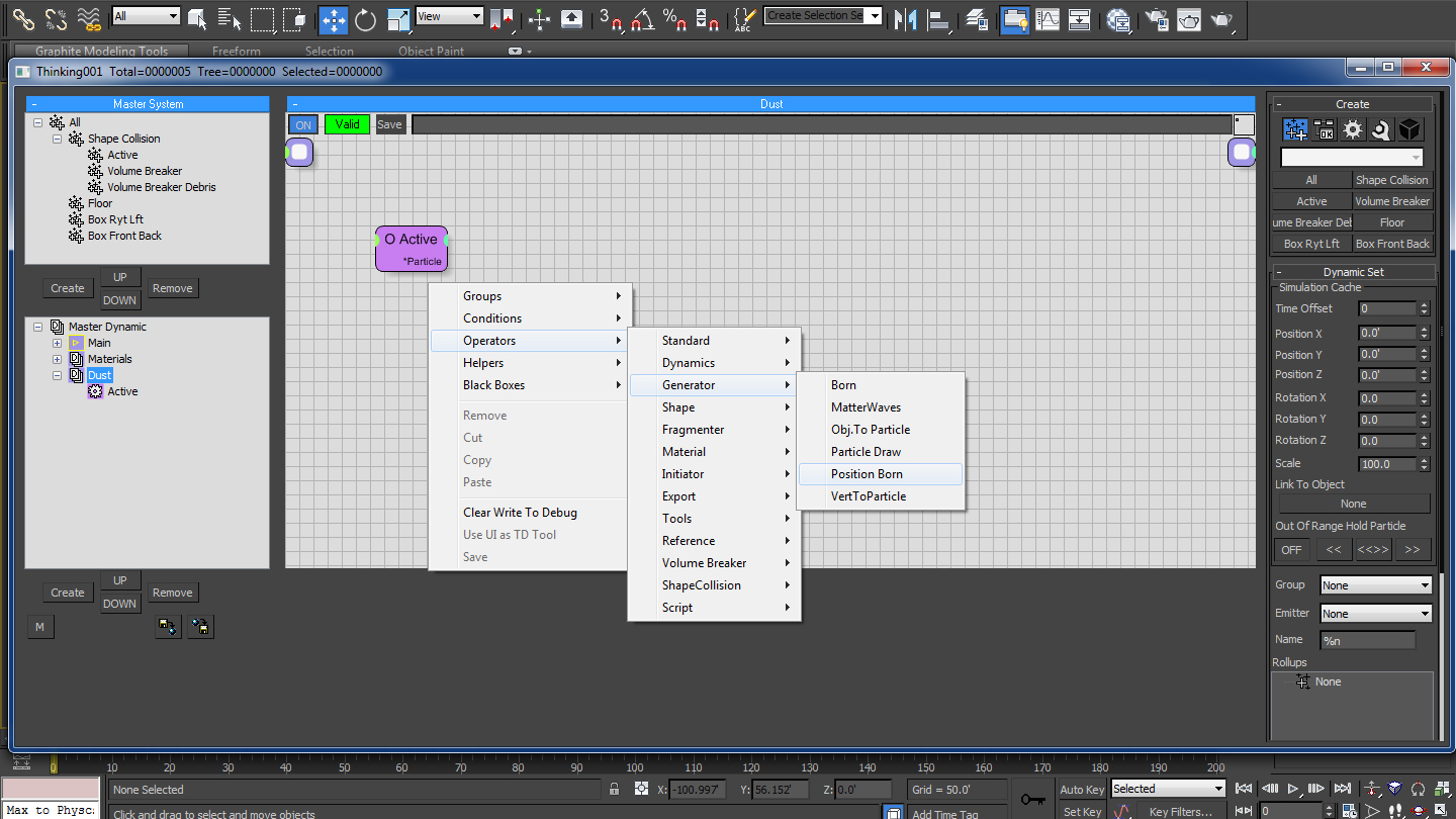
Fig 04.1
04.2 We will also create a new group wit h the name of ‘Dust’. Change the group color to brown so that it will be easier to differentiate inside the view-port. Select Master Dynamic and select ‘Dots’ as the display from the drop-down menu.

Fig 04.2
04.3 Select the ‘Position Born’ operator and Decrease the ‘Life Span’ to ‘15′ while increasing the ‘Speed’ to ’35’ and ‘Variation’ to ’20’. Turn on the ‘Particles / Sec’ option from the ‘Position Burn’ parameters.

Fig 04.3