Introduction to Thinking Particles
01.1 Create a basic scene with a square flat box having a higher number of segments defining the floor and a sphere which we are going to use as the breakable object. Place the sphere in the air at a respectable distance so that we will get enough distance in order to get the breaking of the sphere.
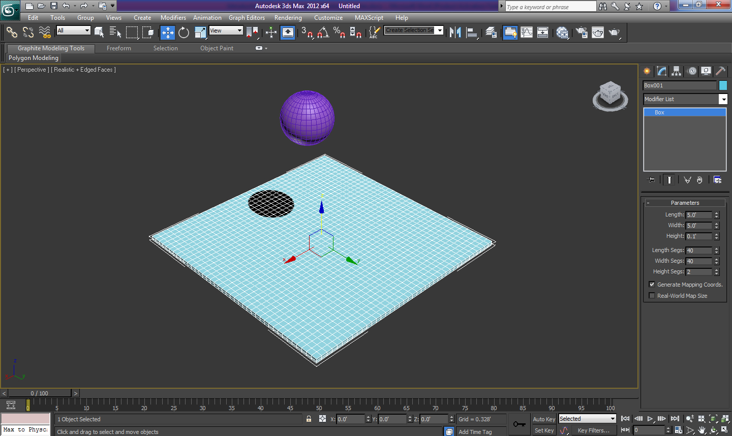
Fig 01.1
01.2 Create the ‘TP’ object by choosing ‘Thinking’ from the Particle Systems section under Create > Geometry panel. Hit ‘Properties’ button in order to access the Thinking Particles interface. Create two groups inside Master System with the name of ‘Sphere’ and ‘Floor’ respectively.
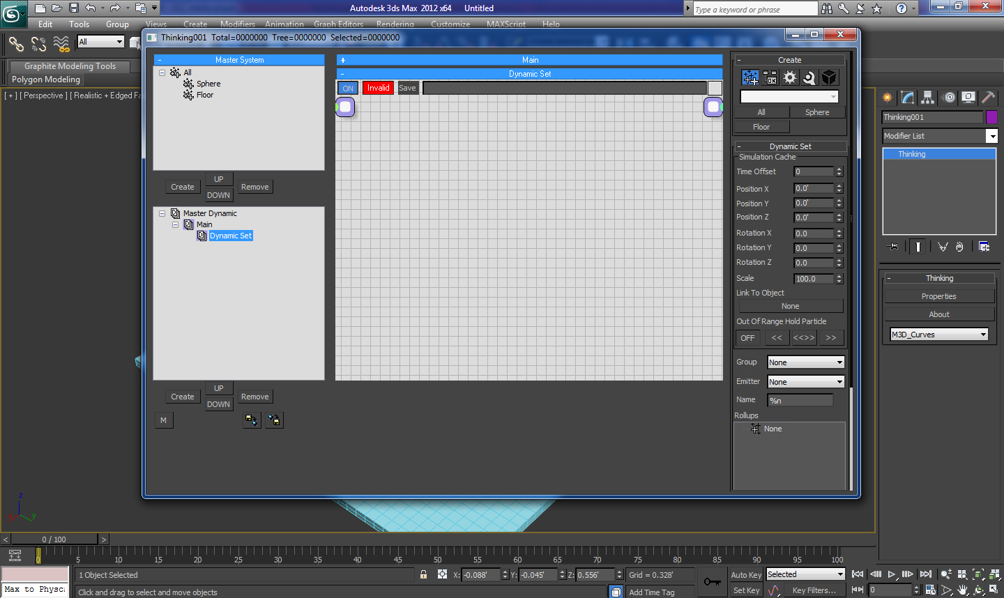
Fig 01.2
02.1 We will now create a system with the name of ‘Main’ by hitting the ‘Create’ button under Master Dynamic panel. This is going to be our main container in which we are going to place the rest of the systems. Create another system with the name of ‘O2P’ inside the ‘Main’ system. We will now create an ‘Obj.To Particle’ node inside the ‘O2P’ system which will help us in converting the objects into particles, right click and select ‘Operators > Generator > Obj.To Particle’.

Fig 02.1
02.2 Inside ‘Obj.To Particle’ parameters press ‘Pick’ and select Sphere from the viewport in order to convert it into a particle. Change the group to ‘Sphere’ and track to ‘Object To Particle’. Check instance shape in order to convert the instanced geometry of the object into particle and leave the original object as it is. Hit ‘hide’ in order to hide the original object. This might lead to the disappearance of both original as well as instanced object from the viewport. But the actual fact is that the instanced geometry is hidden because we have not selected the ‘Show Mesh’ option from the Master Dynamic properties.

Fig 02.2
02.3 Create a copy of the ‘Obj.To Particle’ node by pressing ‘Shift’ while dragging the node. Remove the sphere from the objects list and load the Box object. Change the group to ‘Floor’ and track to ‘Object To Particle’. Check ‘instance shape’ and hit ‘hide’.

Fig 02.3
03.1 Change the name of the Dynamic Set having the Obj.To Particles nodes to ‘Geometries’. And create another system with the name of ‘Gravity’ inside the ‘Main’ system. Click once on the new ‘Gravity’ system in order to load its hierarchy mode display and rope in ‘Sphere’ group by selecting it from the right click menu, ‘Groups > Sphere’.

Fig 03.1
03.2 Add the ‘Force’ Dynamic Operator by selecting it from the right click menu, Operators > Dynamics > Force. Increase the Force ‘Strength’ parameter to 5.0’. Append the ‘Particle’ output of Sphere group node into the ‘Particle’ input of Force node.
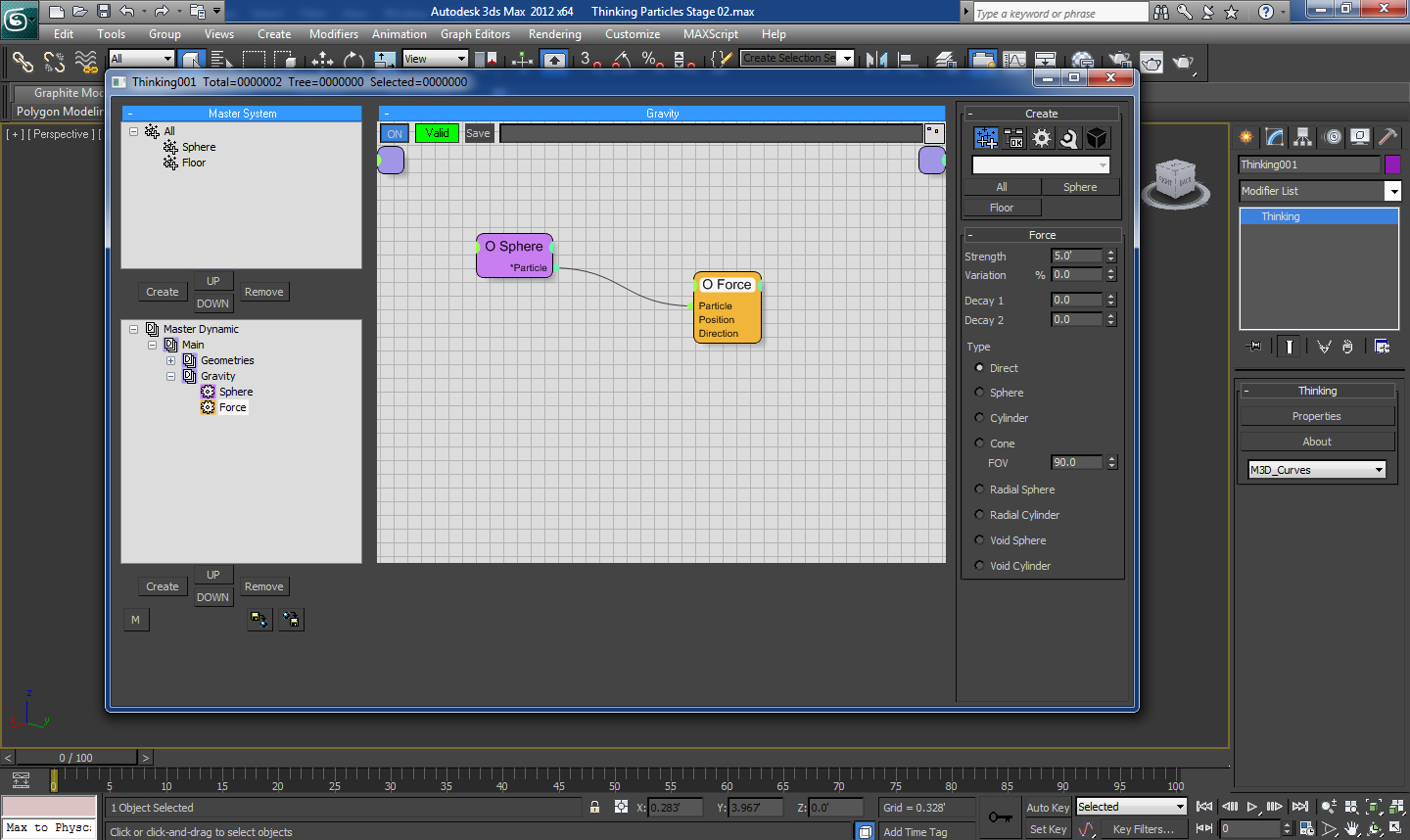
Fig 03.2
03.3 Also add the ‘Point3’ Standard Helper object from ‘Helpers > Standard > Point3’ from the right click menu. Change the ‘Z Value’ to – 1.0 in order to apply the force in Z axis. Append the ‘Vector’ output of Point3 node into the ‘Direction’ input of Force node. We will notice that the sphere has started moving downwards as we wanted but it is also piercing down the floor object.
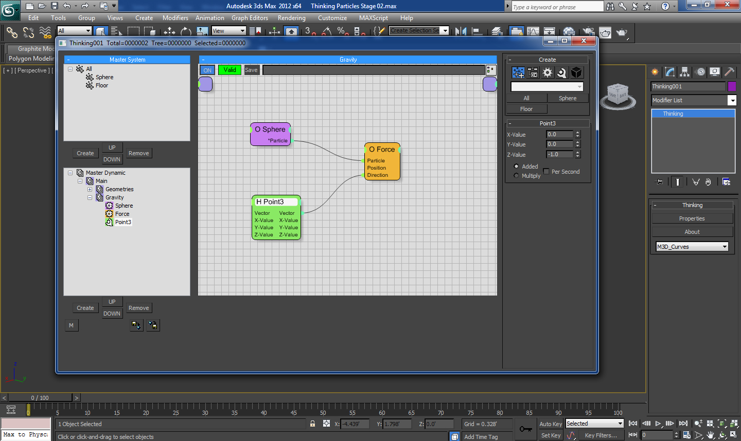
Fig 03.3
04.1 Now we are going to make the sphere collide with the floor with the help of a Shape Collision node. So in order to add it into the net work we have to create another Dynamic set inside the ‘Main’ Dynamic set with the name of ‘Shape Col’. Add a Shape Collision node inside it from the right click menu Operators > Shape Collision > SC.
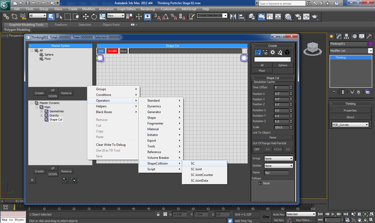
Fig 04.1
04.2 Inside the SC parameters select the Group as ‘Sphere’ and Deflector as ‘Floor’. Play the simulation now in order to notice the sphere getting collided with the floor as we wanted.

Fig 04.2
05.1 Create another Dynamic set inside the ‘Main’ set with the name of ‘Volume Breaker’ as we are going to work on the ‘Volume Break’ node for destruction of sphere on collision, inside this set. So in order to do that rope in the ‘Sphere’ group from the right click menu Groups > Sphere.

Fig 05.1
05.2 Append a ‘Volume Break’ node onto it again from the right click menu Operators > Volume Breaker > Volume Break. Select the ‘Sphere’ from the select ‘Group’ dropdown menu inside the ‘VolumeBreak’ parameters tab. Increase the ‘Activate’ value to ‘70%’ in order to activate the fragmentation.

Fig 05.2
05.3 Move down to ‘Volume Breaker’ tab in order to decrease the ‘Raster’ value to ‘10%’ in order to decrease the bondage between the fractured parts of the object. We will also increase the ‘Density’ to ‘2500’ in order to increase the number of fractures.
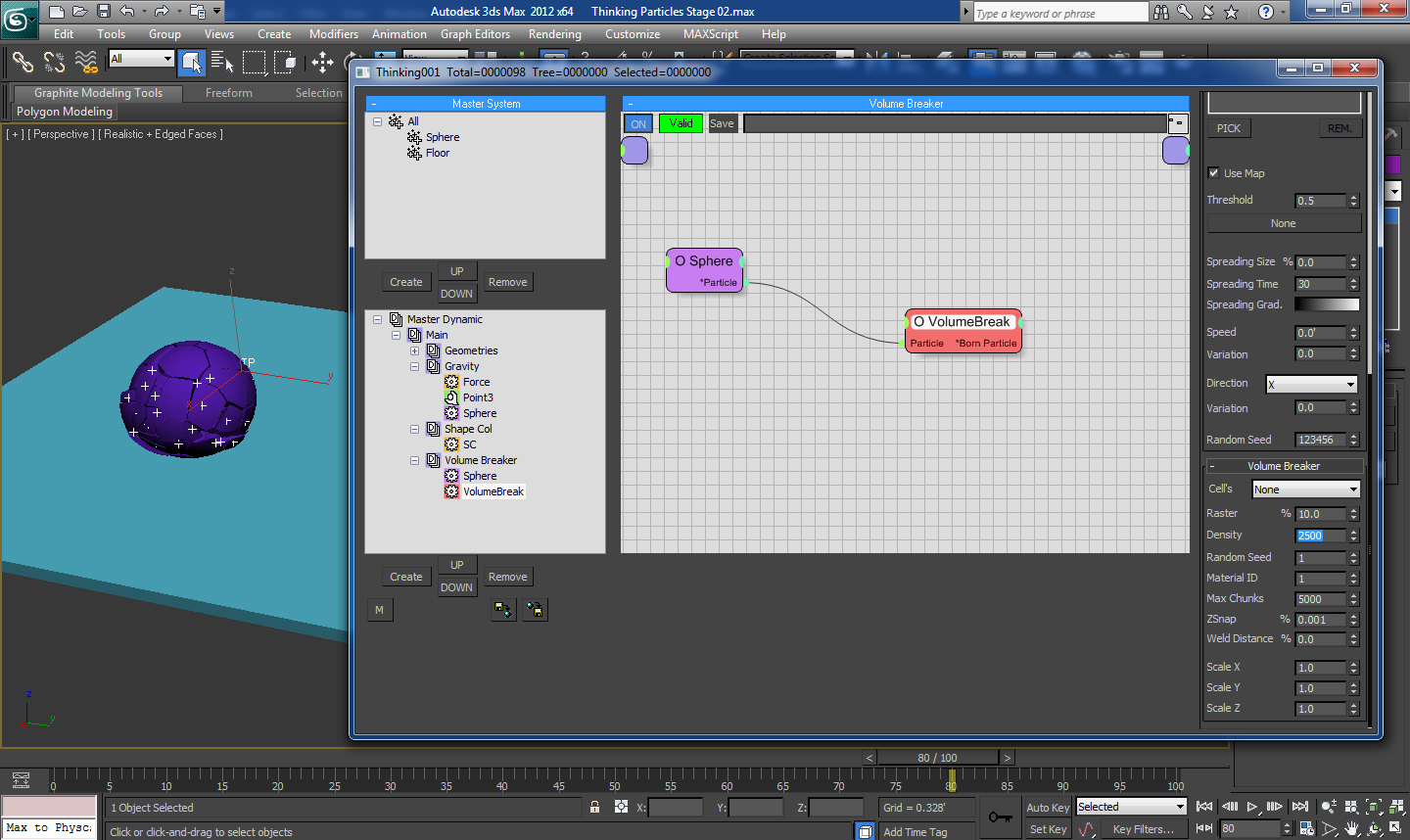
Fig 05.3
06.1 Create a new group with the name of ‘Shape Col’ and drag and drop the ‘Sphere’ group inside it, in order to create the ‘Sphere’ group a sub group of ‘Shape Col’ group. Create another sub group inside it with the name of ‘Frags’. Select the ‘Shape Col’ Dynamic set and change the ‘Group’ to ‘Shape Col’. Also change the ‘Group’ inside ‘Volume Break’ Dynamic set to ‘Frags’.

Fig 06.1
07.1 In order to view the simulation without any problems it will be a good idea to cache it onto the hard disk. We can do the same by right clicking on the ‘Main’ Dynamic set inside ‘Master Dynamic’ panel and selecting ‘Cache Record’. Select the desired folder in which we want to save the simulation and hit ‘Save’.

Fig 07.1